What's different about an elevator family that originates outside the US? It might be called a "lift"instead, or "Ascensore" (as Italians call it), but other than that, the clear conclusion we can all draw is that our European counterparts know how to use Revit really well too ;)
My good Italian Revit buddy Diego Minato, aka "DR. GJIOM" of the blog RevitLandia and moderator on revitforum.com, recently shared a tutorial on an elevator family he created and trusted me to translate it in English. It served to brush up my Italian (technical computer jargon in Italian is quite new to me!) and had fun doing it. He is kindly letting me post it here and hopes you find it informative, useful and educational. Per conto di tutti i Revitisti in questa parte del mondo...grazie Diego!
You can download the family by registering for free and then following this link. If you have trouble, post a comment at the end of this article. Browse through the download section and you'll find some very interesting families and videos about them too.
1. Description
This is not just a simple family but a complete elevator system for 4 levels.
Not only can one vary the height of each level independently, but also the cabin and guide rail heights.
The system is made up of the cabin, the doors at each level and the guide rails.
The geometry is quite simple/generic, but can be easily modified to suit your needs...the scope is purely for architectural planning.
The door opening was also parameterized...which obviously only opens at the level where the cabin is.
1.1 Using the family Place the family in the plan view associated to the lowest level.
If necessary, create new types (by duplicating existing types and modifying as required) so you can adjust the various parameterized dimensions that control the cabin and other accessories.
1.1.1 In a plan view, adjust the guide rail locations by moving the grip handles that appear when the family is selected, or go to the properties window and modify the appropriate instance parameters.
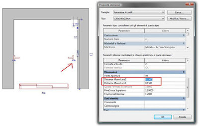 1.1.2
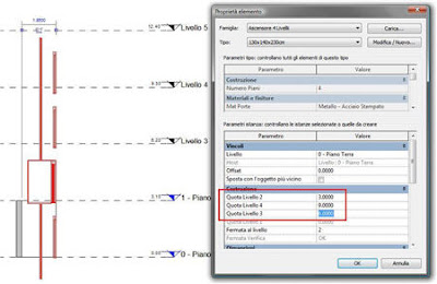
1.1.2 In a section view, measure the distances for the base & top guide rail extensions and each level’s elevation with respect to the hosting level; then input them in the properties dialog as shown below.
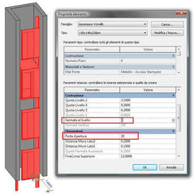
 1.1.3
1.1.3 Input the level at which you want the cabin to stop and the percentage “closure” of the doors (a value of 100 means the doors are 100% closed).
2. Adding one or more levels
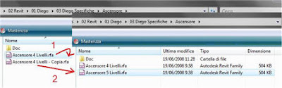
Duplicate the family file and rename…I suggest adding the number of desired levels to the family filename.
 2.1
2.1 Open the new family in Revit.
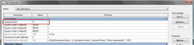
2.2 On the Family design bar, click Family Types.
Increment the parameter “Numero Piani” (number of levels) to the desired quantity of levels. In this example we will use 5, which will be one additional level to the number of levels in the original family.
 2.3
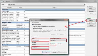
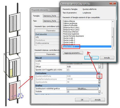
2.3 Add Parameter button...
Define a new parameter and call it “Quota Livello 5” (Elevation Level 5) of type “Length” and group it under “Construction” as an “Instance” parameter. Click OK.
Repeat the same procedure to add more parameters with the same settings and appropriate names when you want to add more levels to the family.
Once created, assign a provisional elevation value to the parameter/s. The actual elevations will be defined in the Family Types dialog once the family is loaded and inserted into the project environment.
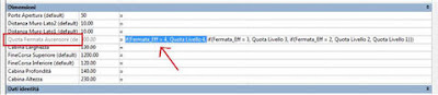
2.4 Quota fermata (Stop height)
Select the first part of the formula for parameter “Quota fermata ascensore” (Elevator stop height) up to and including the comma before the first nested “IF” statement and copy to clipboard (Ctrl-C).
Place the cursor at the beginning of the formula and paste (Ctrl-V). Modify the pasted part with the name and value of the highest level (5) and the parameter name that contains the new level height.
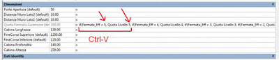
Place the cursor at the end of the formula and close with an additional parenthesis (curved bracket).
The resulting expression should look similar to the following:
if(Fermata_Eff = 5, Quota Livello 5, if(Fermata_Eff = 4, Quota Livello 4, if(Fermata_Eff = 3, Quota Livello 3, if(Fermata_Eff = 2, Quota Livello 2, Quota Livello 1)))), where “Fermata_Eff” is a calculated parameter with built-in error checking.
This procedure has to be repeated if you add more than one level to the family.
Finally, close out of the Family Types dialog.
2.5 Adding doors In a 3D view, select one of the doors and copy to clipboard (Ctrl-C).
From the Menu bar > Edit > Paste Aligned > Same Place.
A pop-up will warn you that there are identical instances in the same place. Ignore it.
With the same selection active (don’t click on other objects), click on the properties button; otherwise, right click > Element Properties.
If you inadvertently lose your selection…click on the element you just copied from and one of the two instances will be selected...
In the Element Properties dialog, click the little gray button to the right of the parameter “QuotaLivelloPorte” and select the parameter that reports the height of the new stop. Ok, Ok.
 2.6 Testing/Flexing
 From the Design Bar > Family Types…set the door aperture to 50 and vary the elevator stop level (Fermata al livello) by clicking on the little arrow buttons (integer parameter). Click Apply after each modification to verify that the cabin stops at the appropriate level and that the doors open and close correctly.
Save and load the family into your project. As mentioned in section 1.1 and subsequently explained, make further modifications to the family to suit your precise needs.
3. Removing one or more levels Duplicate the family file and rename…I suggest adding the number of desired levels to the family filename.
3.1 Open the new family in Revit.
3.2 On the Family design bar, click Family Types
Decrease the parameter “Numero Piani” (number of levels) to the desired quantity of levels. In this example we will use 3, which will be one level less than the number of levels in the original family.
3.3 Remove Parameter button...
Click on the parameter that defines the level you want to remove; in this example “Quota Livello 4 (Height of Level 4) and then click on the “Remove” button.
If you have additional stops you want to remove, repeat the procedure for the other level parameters “Quota livello ...” to remove them.
3.4 Quota fermata (Stop height)
Select the first part of the formula for the parameter “Quota fermata ascensore” (Elevator stop height), up to and including the comma before the first nested “IF” statement and delete.
Also delete the last parenthesis at the end of the formula (curved bracket).
3.5 Removing doors
In a 3D view, select the door that pertains to the highest level (or those that pertain to the levels you want to remove from the top) and delete.
3.6 Testing/Flexing
Similar to section 2.5...
Save and load the family into your project. As mentioned in section 1.1 and subsequently explained, make further modifications to the family to suit your precise needs.


 Now we don't typically use roofs by extrusion for flat roofs, but this was just to illustrate a point. I would rather come up with one rule and stick to it, such as see roofs by extrusion to consistently grow upwards like their footprint counterparts. You can argue that when sketching by extrusion, you know where the top of your roof is, however this seems to be a topic that can be argued from both sides. At least now you know the difference between the two modes!
 You can set an opening cut in hosted families to be transparent in 3D and/or Elevation. Above you can see the default settings. The reason I wasn't aware of it was possibly because material transparency is not respected in elevations. A common technique to get window glazing to show transparent in elevation is to use a 3D view oriented to an elevation, and thus the opening shows transparent due to the setting above. That's my excuse and I'm sticking to it!


